Repairing a dead TP-Link TL-PA211 Powerline Ethernet Adapter (Part 1)
Posted by Kev on
I’ve been using a pair of TP-Link Powerline TL-PA211 Ethernet Adaptors for about 18 months and they’ve been brilliant; far superior to using a wireless signal to bridge the house sized gap between the ADSL modem and my computers.

Within the space of about 6 weeks the adaptors died in the same way, both suddenly not powering on, showing no signs of activity whatsoever. I bought some new devices and went to throw the TP-Link ones in the recycling but, unable to throw them away without knowing why they had stopped working, I decided to open them up and have a look inside.
They were tough to open but I eventually prised them apart where I noticed that both had the same fault! A single failed capacitor was the culprit. I know my way around a soldering iron and a circuit board but only usually enough to re-flow existing solder around a problem joint or broken track but after seeing that the replacement capacitors I needed only cost 99p from eBay I decided to attempt the repair.

Dismantling the TP-Link TL-PA211 Powerline Ethernet Adaptor:
Undo the only screw keeping the thing together. It’s located underneath the information label on the plug side. This will break your warranty if you still have one. Only continue if you are out of warranty or happy to never be able to return it.
Once you have removed the screw you can pop off the white plastic cover from the black base. I used a small screwdriver to prise it apart. It was quite tight and I did break one of the plastic clips so be careful 🙁
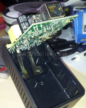
At this point of the dismantling I wasn’t sure how to go ahead. Something was holding the PCB down to the base of the casing, preventing it from lifting up, but still allowing for some movement. I managed to get the PCB out by pushing the network port side in and pushing up. It took a lot of force and I broke the plastic rod of the push button reset switch but I eventually got it open. This reveals what was stopping the PCB from coming out.
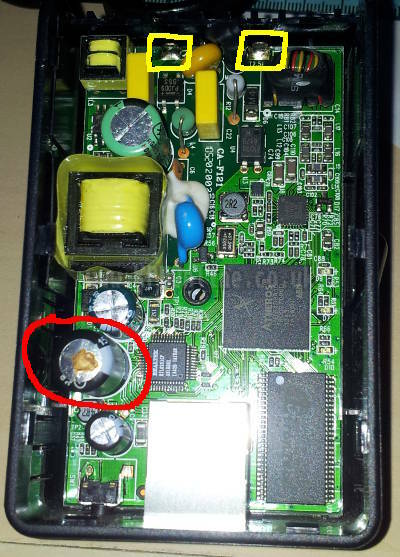
As you can see from the picture the Live and Neutral pins of the plug attach to two metal strips that are soldered to the top edge of the PCB (Yellow). I really should have de-soldered these before attempting to remove the PCB. If you don’t want to risk damaging the network port or reset switch then de-solder these strips before proceeding. You can also see my damaged reset button. I wasn’t too bothered about the damaged reset button as it still worked. I’d need to stick a pen in there in future to reach the switch. One benefit of this is that nobody will accidentally be able to press the switch and reset my network.
You should now have a fully opened adaptor with the PCB accessible on both sides.
I’ll cover the actual repair in my next post and show you just how simple it was.
Disclaimer: If you do attempt to open up and fix your Powerline adaptor I cannot be held responsible for any damage that may occur to you, the adaptor or your surroundings. Be careful! Make sure you replace the parts with the same type and rating.
Comments from wordpress will appear here once I’ve copied them over 👍
Categories:
Repair← Older posts
GooGone? DuckDuckGo!
Newer posts →
Repairing a dead TP-Link TL-PA211 Powerline Ethernet Adapter (Part 2)